
Item no.: F19
RLC circuit has a very important feature, that is, the produced amplitudes of circuit-current will closely depend on the input frequency. Generally speaking, partial signal will be filtered, but partial might be augmented as several power sources with different frequency, in the circuit, are delivered simultaneously. Here amplified signal of frequency is primarily determined by the value of L and C selected. However the converse effect will appear as the higher resistance R is involved. Thus the so called “filter effect” might be taken as an important characteristic in RLC circuit. In addition, RC circuit, in the absence of power supplier, is usually performed as a convertor of electric energy in the envelope of electric field. Here the electric energy charged into or discharged from capacitor C is based on the demand of current flow in circuit. That might be also used as “Quick Battery” existing in almost all electronic circuits.
Objectives
- Investigate the time constant for value of C in charging or discharging process of RC circuit.
- Learn the resonant-frequency response for RLC in series deployment.
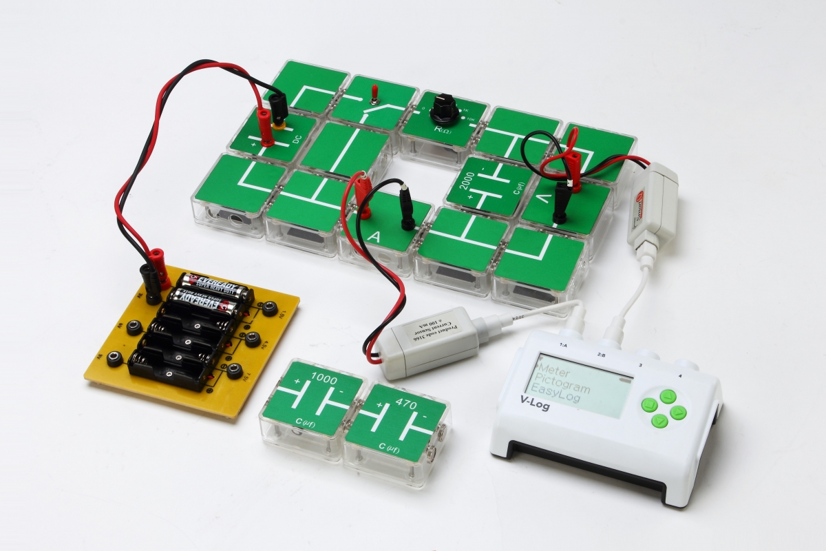
Experiment—RC
In RC circuit, the voltage across capacitor is relative to the charge and discharge time of capacitance. In fact, dimensionless-time value of R*C we said it as a time constant for
circuit. By way of time varying voltage profile accessed from charging or discharging process, the needed value of capacitor might be determined.
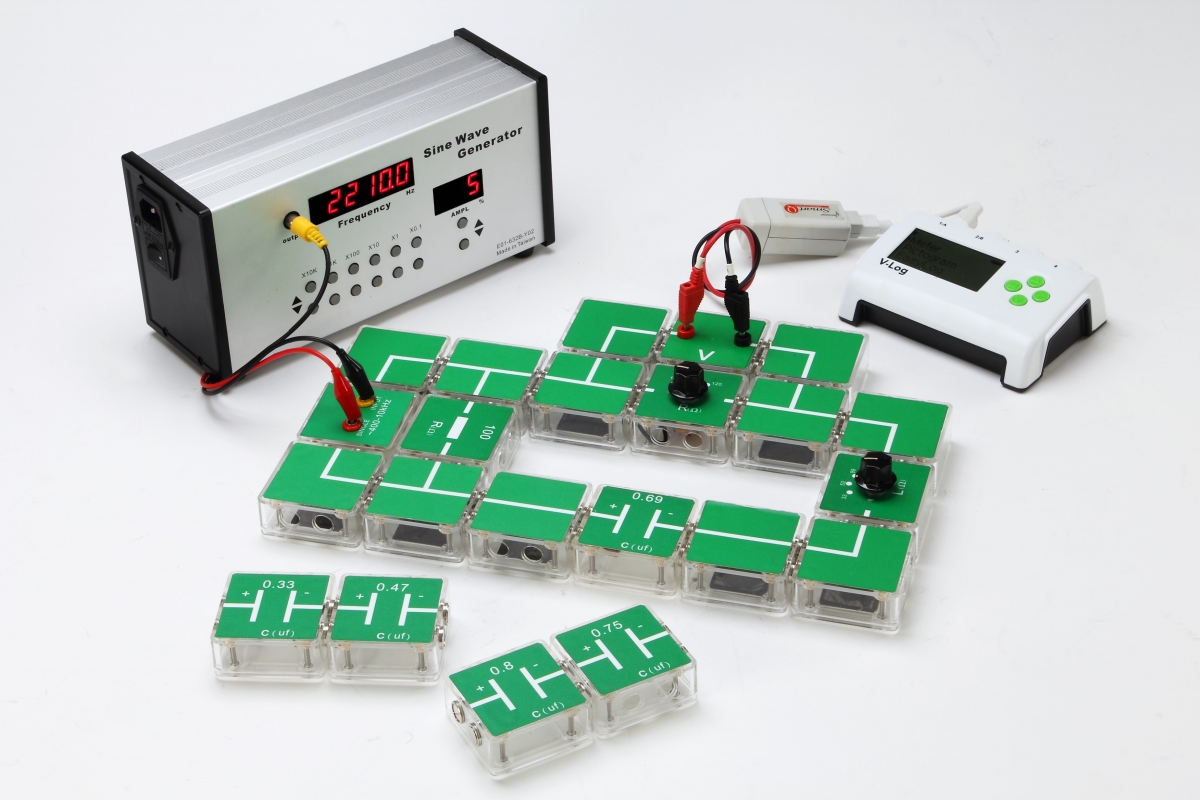
Experiment—RLC
A fundamental RLC series circuit, figured right, is primarily constituted by electric resistor R, inductance (L), capacitance (C) as well as AC voltage. Specify a set of L,C in circuit and a parallel voltmeter across the resistor R, a varying voltage signal might be readable from voltmeter while adjust the driving frequency of power source. As the regulated frequency is close to natural oscillating frequency yielded below, signal resonance will occurs in RLC circuit and the maximum voltage could be displayed on the panel of voltmeter. Here the resonant frequency will be also available to the fluctuated frequency accessed from the circuit-current and voltage signal across the resistance. Referred to the so called “resonant frequency” formulated above, corresponding response might be figured below, and here the value of gain, defined as the ratio of terminal voltage and power supplied voltage, might be estimated on the profile sketched below.
實驗項目:
- RLC共振
- RC充放電
實驗器材:
- 導線
- 電流計接線盒、電壓計接線盒
- 轉向開關
- 交流信號源接線盒
- 直流電源接線盒
- 三段式電感器
- 電阻器10/100/1k/10kΩ
- 電阻器100/110/120Ω
- 電阻器100Ω
- 電容2000/1000/470μF
- 電容 0.33/0.47/0.69/0.75/0.8μF
- DC電池盒
- 連接導線
- RC插頭轉香蕉插頭信號線
- 選購品或自備品:
- 正弦波信號產生器
- Datalogger 電腦數據擷取器
- 電壓感測器
- 電流感測器